Software Engineering and Software Testing > Software Design > Use Case Model
Use Case Model
A Use Case Diagram is a type of Unified Modeling Language (UML) diagram that shows the interaction between actors (users or external systems) and a system under consideration to complete specific goals. Use cases represent the different ways in which a system can be used by the users. Example: A Library Information System (LIS), the use cases could be:
- issue-book
- query-book
- return-book
- create-member
- add-book, etc
Actually, use cases correspond to the high-level functional requirements. The use cases partition the system behavior into transactions.
Purpose of use cases
From use case diagram, it is obvious that the utility of the use cases are represented by ellipses. They along with the accompanying text description serve as a type of requirements specification of the system and form the core model to which all other models must conform.
The purpose of a use case is to define a piece of logical behavior without revealing the internal structure of the system. The use cases do not mention any specific algorithm to be used or the internal data representation, internal structure of the software.
For example, the mainline sequence of the withdraw cash use case supported by a bank ATM drawn, complete the transaction, and get the amount. Also variations or alternate scenarios may occur, if the password is invalid or the amount to be withdrawn exceeds the amount balance. The variations are also called alternative paths.
A use case can be viewed as a set of related scenarios tied together by a common goal. The mainline sequence and each of the variations are called scenarios or instances of the use case. Each scenario is a single path of user events and system activity through the use case.
Actors
Actors are external entities that interact with the system. An actor may be an users or other system, or a hardware device. In the context of a Use Case Diagram, actors initiate use cases and receive the outcomes.
System Boundary
System boundary is a visual representation of the scope or limits of the system. Boundary helps to establish a clear distinction between the elements that are part of the system and those that are external to it. A system boundary is represented by a rectangular box that surrounds all the use cases of the system.
Use Case Diagram Relationships
In a Use Case Diagram, relationships depicts the type of interactions between actors and use cases. There are different types of relationships as follows:
Association Relationship
Association Relationship represents a communication or interaction between an actor and a use case. A line connecting the actor to the use case are used for this.
Example: Online Banking System
- Actor: Customer
- Use Case: Transfer Funds
- Association: A line connecting the “Customer” actor to the “Transfer Funds” use case, indicating the customer’s involvement in the funds transfer process.
Include Relationship
Include Relationship indicates that a use case includes the functionality of another use case. It is denoted by a dashed arrow pointing from the including use case to the included use case. This relationship promotes modular and reusable design.
Example: User registration
- Use Cases: input name and other information, add an image
- Include Relationship: The “User registration” use case includes the functionality of “Add Image.” Therefore, User registration includes the action of adding an image.
Extend Relationship
The Extend Relationship depicts that a use case can be extended by another use case under specific conditions. It is represented by a dashed arrow with the keyword “extend.” This relationship is useful for handling optional or exceptional behavior.
Example: Flight Booking System
- Use Cases: Book Flight, Select Seat
- Extend Relationship: The “Select Seat” use case may extend the “Book Flight” use case when the user wants to choose a specific seat, but it is an optional step.
Generalization Relationship
The Generalization Relationship establishes an “is-a” connection between two use cases, indicating that one use case is a specialized version of another. It is represented by an arrow pointing from the specialized use case to the general use case.
Example: Vehicle Rental System
- Use Cases: Rent Car, Rent Bike
- Generalization Relationship: Both “Rent Car” and “Rent Bike” are specialized versions of the general use case “Rent Vehicle.”
Representation of Use Cases
Use cases can be represented by drawing a use case diagram and writing an accompanying text elaborating the drawing. In the use case diagram:
- Each use case is represented by an ellipse with the name of the use case written inside the ellipse. All the ellipses (i.e. use cases) of a system are enclosed within a rectangle which represents the system boundary.
- The name of the system being modeled (such as Library Information System) appears inside the rectangle.
- The different users of the system are represented by using the stick person icon. Each stick person icon is normally referred to as an actor.
- An actor is a role played by a user with respect to the system use.
- It is possible that the same user may play the role of multiple actors.
- Each actor can participate in one or more use cases.
- The line connecting the actor and the use case is called the communication relationship.
- Both the human users and the external systems can be represented by stick person icons.
- When a stick person icon represents an external system, it is annotated by the stereotype <>
Use Case diagram of an Online Shopping System:
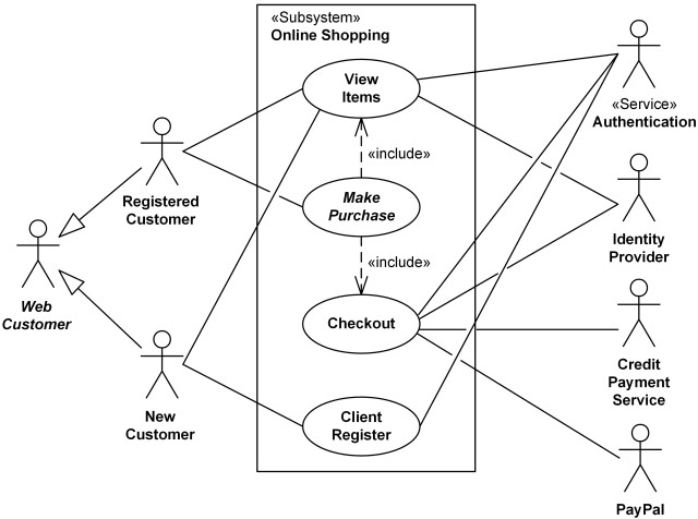
- Actors: Customer, Admin
Use Cases: Browse Products, Add to Cart, Checkout, Manage Inventory (Admin)
Relations:
- The Customer can browse products, add to the cart, and complete the checkout.
- The Admin can manage the inventory.

Text description
Each ellipse on the use case diagram should be accompanied by a text description. Text description should define details of the interaction between user and computer and other aspects of the use case. It should include all the behavior associated with the use case in terms of the mainline sequence, different variations to the normal behavior, the system responses associated with the use case, the exceptional conditions that may occur in the behavior, etc.
Example:
U1: register-customer:
Using this use case, the customer can register himself by providing the necessary details.
Scenario 1: Mainline sequence
- Customer: select register customer option.
- System: display prompt to enter name, address, and telephone number.
- Customer: enter the necessary values.
- System: display the generated id and the message that the customer has been successfully registered.
Scenario 2: at step 4 of mainline sequence
System: displays the message that the customer has already registered.
Scenario 3: at step 4 of mainline sequence 1.
System: displays the message that some input information has not been entered. The system displays a prompt to enter the missing value.
What are the Processes of Design?
No More
Feedback
ABOUT
Statlearner
Statlearner STUDY
Statlearner